Echoes of Ragnarok: 3D Printing Overview (Part One)
Alexander "Elouan" Groom
The players at Rhiassa’s most recent event did not just get to go to an event, but also saw the debut of Rhiassa’a 3D printed props. These props were a number of different bones, printed in various colors. For this article, I am going to outline the process we used to create these props, along with some of the issues we encountered along the way.
While there are many notable differences, a 3D printer and a 2D printer both operate on similar principles. They take some sort of digital file, and turn it into a physical representation of that digital file. In the case of a 2D printer, this is usually some sort of word document or PDF. For 3D printers, this is a CAD (computer aided design) file.
CAD files are generated in various different CAD softwares, and have a variety of different file types. I could go on for an entire article about this (and, if there is interest, gladly will!), but the kind we are concerned with is called a .stl file. A “.stl” file, without getting too technical, is what most slicer softwares use to generate files for 3D printers.
Slicer software is software that takes a CAD file, and turns it into a set of instructions for a 3D printer to use. There are a variety of slicer softwares available; some are even specialized for specific makes and models of 3D printers. In Rhiassa’s case, we use a Makerbot Replicator 2X (before anyone asks-yes, most of that is in fact meaningless buzzwords) 3D printer, which has it’s own slicer software (called Makerbot Desktop-real creative in the naming department, that company).
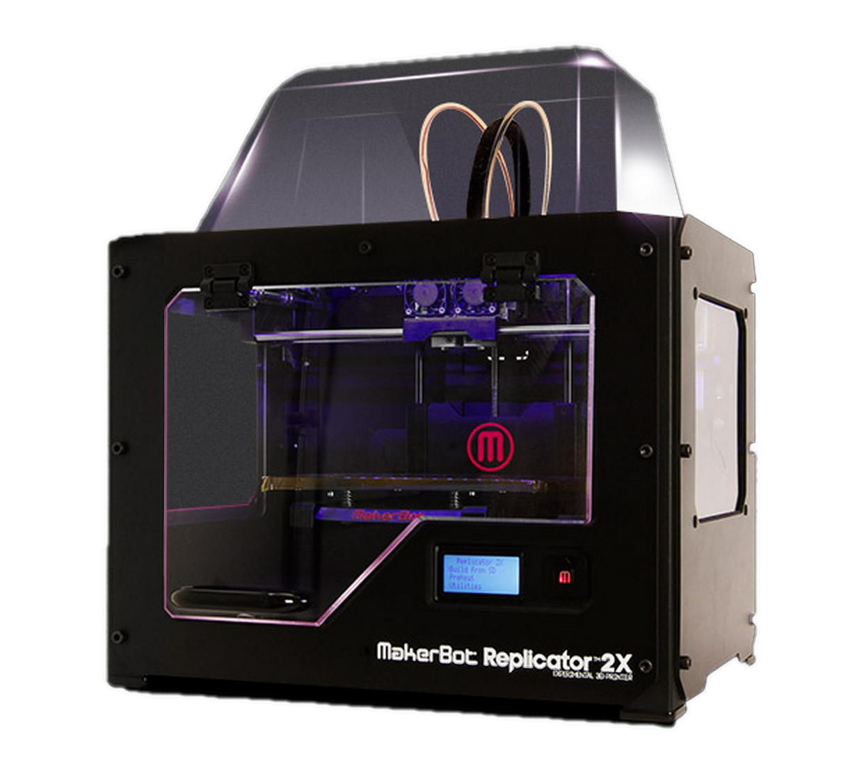 |
| A Makerbot Replicator 2X. This was useful for us, as it has two printing heads, each of which can extrude either a different material or different colored plastic. This saves time and effort on unloading and reloading filament. |
Anyway, there are two basic ways to get a CAD file: make your own, or grab one from an online depository. For these parts, Rhiassa used both methods,.
I’m not going to talk much about making your own CAD file here. If there’s interest, I will do another write up dealing specifically with how to make your own CAD file. Long story short, there are a variety of softwares available for making CAD files, ranging from free online services that favor simplicity (Tinkercad comes to mind) to high end, expensive softwares that favor complexity. In general, the more complex your part, the harder it will be to model with simple software; at some point, you either have to make some concessions and simplify your part, or figure out how to access and use one of the more expensive and complicated softwares. For reference, the raven skull, fang, and vertebra were custom made in SolidWorks. Final note on making your own CAD files: make two copies; one in the format preferred by the software you are using, and a .stl for 3D printing purposes.
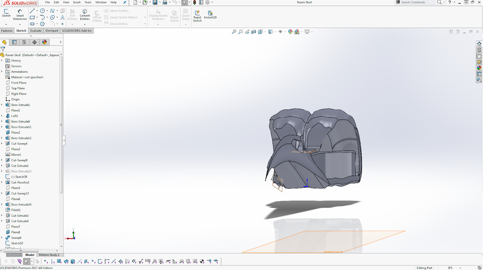 |
| The raven’s skull, as seen in SolidWorks. This was a custom CAD model built entirely from scratch. This part took several hours of work, a lot of which was fixing errors within SolidWorks. This is as someone with a decade of CAD experience, so keep in mind that it may take longer depending on the software you are using and your level of experience if you choose to go this route. |
It is far easier to just grab a CAD file from an online depository. This is what we did for the finger bone and wishbone. My personal favorite depository for CAD files is Thingiverse (no, I don’t have an endorsement deal with them-though if any of you have the power to offer one, I am not saying no.) Thingiverse is specifically for 3D printing, too-a lot of the files include additional information on the best print settings to use. This also means that the parts have been proven to print well (which, if you are making your own CAD files, is far from guaranteed, as I will show).
Speaking of online depositories for CAD files: one of my goals is to get more people in Realms involved in doing these sorts of things. To that end, I have started a “Realms CAD Files” google (link: https://drive.google.com/drive/folders/1ZL6PU3Jpfu7RRyPsaFNUg24XIvcJl1N2?usp=sharing ) drive for storing CAD files, and will be adding the custom CAD files we made for this event to it, in both .sldprt (SolidWorks’ standard save format) and .stl format. Anyone is welcome to use these files for their own event. If anyone has any files of their own they would like to add for community use, they are more than welcome to do so. Also, if anyone has any problems accessing this, please let me know.
Now that we have a CAD file in the proper format, we come to using the slicer software. As I previously mentioned, the slicer software takes a CAD file, and turns it into a set of instructions for the 3D printer. To do this, you need to specify a couple of things. First, you need to load your part into the slicer software. With Makerbot Desktop, this is as simple as opening the CAD file with the software. Next, you can play around with the scale, orientation, and location of the part. If you didn’t dimension your part properly, you may need to scale it to get it to be the appropriate size. You also want to orient your part such that the bottom surface is relatively flat, and there are as few as possible overhangs.
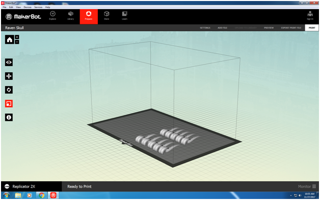 |
| The raven skull, properly placed and scaled. Multiple skulls are present so that multiple skulls can be printed in one go. The surface chosen to be the bottom surface of this part was intuitive; it was the flattest surface, and minimized overhangs in cosmetic areas. In this case, the scale was chosen by setting a particular dimension to 50mm; Makerbot Desktop automatically scales the rest of the dimensions proportionally. |
Next, specify if you want a raft and a support structure. A raft is a layer of plastic below the part that makes sure that it adheres to the surface you are printing on during the printing process, and peels off the part at the end. This is good, but can leave a rough surface finish on that surface of the part. In general, if the surface finish of the bottom of the part isn’t a concern, you want to use a raft. A support structure is basically plastic that breaks off of the part at the end that is used to print overhangs. If your part has overhangs, you usually want to use a support structure.
Finally, there are a number of settings that can be altered depending on the material that is being printed. Makerbot Desktop is friendly in that it has several settings for a variety of materials stored as presets; in theory, all you do is select the material you are printing with, and the slicer software takes care of the rest. If the slicer software you are using doesn’t have preset materials, or doesn’t have the material you are using, you can almost always find the proper settings for a given material. I personally find that RepRap (link: http://reprap.org/wiki/Printing_materials ) has good information on a variety of materials.
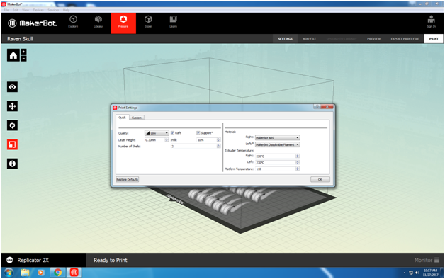 |
| The settings used for the raven skull. I’ve had problems with parts delaminating in the past, so I used a raft. Support structures were enabled due to a couple of overhangs present in the part. Material settings (including the temperature) were defaults saved in the software. Resolution was set to “low” and the layer height set to 30mm as this was sufficient for the level of detail I needed, and would keep the build time to a minimum. Number of shells was set to 2 and infill to 10%, as both of the |